
Many similar cables
Color codes and markings differ only slightly, and the number of cables per product is high.
Wiring combines many similar cables, many small connection points and routing that changes per variant. Arkite projects the route and the connection point directly on the work, step by step.
Last updated
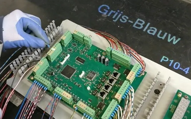
Cabling and wiring covers wire harness assembly, cable routing in machines and vehicles, control cabinet wiring and connecting cables to circuit boards and modules. Each cable has its own color, length and destination.
A cable on the wrong terminal or along the wrong route may pass visual inspection and only fail at functional test or in operation.
Color codes and markings differ only slightly, and the number of cables per product is high.
Terminals and connectors sit close together, so a one-position offset is easy to make and hard to see.
Some variants are built rarely, so operators cannot rely on routine to remember the route.
Reading wiring diagrams takes experience, which slows down the onboarding of new operators.
A barcode scan or the MES selects the job variant, so only the relevant routing and connections are shown.
Arkite projects CAD drawings and images 1:1 on the workbench or board, so the operator follows the route directly on the work.
Each step indicates the cable to pick, its color code and the exact connection point, with detail on the operator screen.
With VALIDATE, the 3D sensor confirms the pick from the correct bin and activity at the correct location.
With VISION, the Vision sensor can check non-rigid shapes such as bent cables, and the presence and position of small parts.
Projects can be created from CAD/CAM input, and drawings can be projected at true scale.
The Arkite RGB sensor reads barcodes, Data Matrix codes and text from the image, and the workflow can branch on the result.
Quality checks with multiple result classes, each with its own rework instruction.
Bring a drawing of one of your harnesses or cabinets to the demonstration.
Arkite
Operator guidance platform
Welcome to Arkite.
Looking to guide, validate and inspect manual work? Choose where you would like to start.
Prefer email? info@arkite.comPrivacy
Your privacy choices
We use analytics to understand how the website is used and, with your permission, to measure the results of our campaigns on LinkedIn and Google. Measurement runs through our own server; no tracking scripts from other companies are loaded in your browser. See our privacy notice.